Sep 17, 2026Applications
Locating, Positioning & Locking Components for Jigs & Fixtures
A practical guide to locating, positioning and locking components for jigs and fixtures, including round and diamond pins, lead-in geometry, bushings and quick-change considerations.
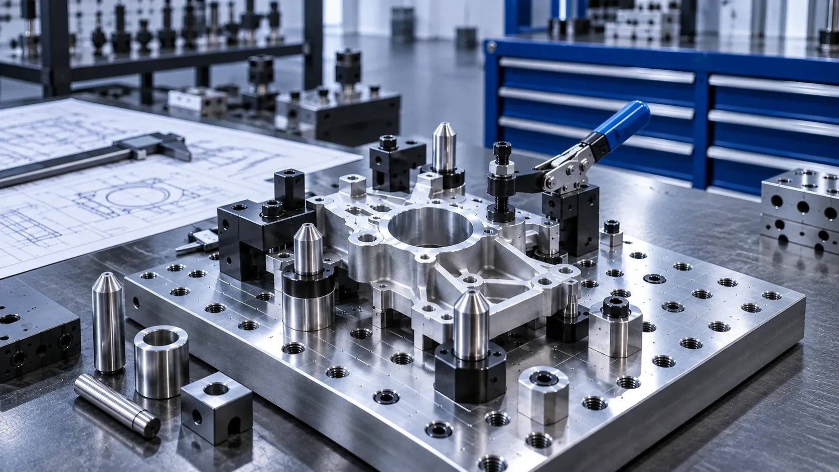
Locating, Positioning & Locking Components for Jigs & Fixtures
Reliable fixturing starts with a simple requirement: the workpiece or tooling must return to the intended position without unnecessary difficulty during loading, adjustment or changeover.
The challenge is that tighter location is not always better. Two locating points can become over-constrained, small hole-spacing variations can cause binding, and a pin geometry that works well for occasional manual loading may be less suitable for frequent insertion or automated handling.
This guide explains the practical role of locating, positioning and locking components in jigs and fixtures, and the key questions to consider before specifying them.
Start with the locating function
Before selecting a component, define what it actually needs to do.
A fixture may need to:
- establish a repeatable datum;
- locate a workpiece from one or more holes;
- guide a part during loading;
- provide repeatable indexed positions;
- align two fixture plates or components;
- retain a removable element;
- support faster fixture or tooling changeover.
These functions should not automatically be assigned to the same component. Separating location, adjustment, locking and release usually makes the selection process clearer.
For a new fixture or replacement component, start by identifying the locating method, mating feature, required movement and how often the component will be loaded, adjusted or removed.
Why are round and diamond locating pins used together?
When a workpiece or fixture is located from two holes, using two fully constrained round locating pins can create problems if the actual center distance between the holes differs slightly from the nominal value.
A common solution is to use a round locating pin as the primary locator and a diamond locating pin as the secondary locator.
The round pin establishes location in two axes. The relieved geometry of the diamond pin constrains the secondary point in one axis while allowing accommodation for small center-distance variation in the other.
The practical result is repeatable location with less risk of redundant constraint and binding during loading or unloading.
This arrangement is particularly relevant when:
- two machined holes establish fixture location;
- repeatable loading and unloading are required;
- accumulated tolerances can affect hole spacing;
- tooling plates or fixture elements must be repeatedly relocated.
The correct fit and tolerance still depend on the actual application. The round-and-diamond principle does not replace an application-specific tolerance review.
Make loading easier without sacrificing location
Accurate location is only useful if the operator or automation system can load the part consistently.
Entry geometry therefore matters.
Chamfers, tapered lead-ins and bullet-nose profiles can help guide a mating hole toward the final locating diameter before precise location is established. This becomes increasingly important when the workpiece is difficult to align visually, when insertion occurs frequently, or when automated equipment performs the loading.
For two-pin arrangements, using different effective engagement heights can also help. The first locator can begin guiding the part before the second locator reaches its final locating interface.
Consider bullet-nose or tapered locating pins when the application needs more lead-in assistance rather than expecting a tight locating diameter to correct a large initial misalignment.
The important distinction is:
lead-in geometry helps the part enter; the locating interface establishes the final position.
Those two functions should not be confused.
Consider wear at the locating interface
Repeated loading creates contact at the pin, hole and mating interface. Over time, wear at these surfaces can affect loading behavior and repeatability.
For frequently cycled fixtures, consider whether the wear interface should be replaceable.
A locating or guide bushing can provide a defined mating interface and, depending on the fixture design, allow the wear component to be serviced without replacing or reworking the complete fixture plate.
This is especially worth considering when:
- loading cycles are frequent;
- the base fixture is expensive to remake;
- maintenance access matters;
- a removable plate repeatedly mates with the same location;
- the locating interface is expected to be a service item.
When specifying a pin-and-bushing arrangement, review the mating diameters, fit, installation method, engagement length and surrounding fixture material together rather than selecting the two parts independently.
Use indexing components for repeatable adjustable positions
Not every fixture feature should be permanently located.
Some applications require a stop, guide, slide, arm or fixture element to move between defined positions. In these cases, an indexing plunger can provide a repeatable mechanical indexing function while still allowing intentional repositioning.
Typical questions include:
- How many positions are required?
- Must the plunger remain retracted during adjustment?
- How often will the position change?
- Is accidental disengagement a concern?
- What space is available for manual actuation?
- What mating feature will receive the indexing pin?
This is a different problem from precision workpiece location. A locating pin establishes a datum or locating relationship; an indexing component is generally used where a movable element must repeatedly return to defined positions.
Selecting between them should start with the required motion, not simply with the component shape.
Separate quick release from precision location
For removable fixture elements, access panels, tooling plates or frequently changed assemblies, ball lock pins and quick-release pins can reduce the time required for assembly and removal.
However, a quick-release component should not automatically be treated as the sole precision locator.
Ask two separate questions:
- What establishes the required position?
- What retains or releases the removable component?
In some designs these functions can be integrated. In others, dedicated locating features establish position while the quick-release component provides retention and fast removal.
For quick-change tooling, the interface between the pin, receiver or bushing, locating features and the surrounding fixture should therefore be considered as a system.
This is particularly important when repeatability after repeated changeovers matters.
Five common fixture problems to check before selecting components
1. The workpiece binds on two locating pins
Review whether the fixture is over-constrained and whether a round-and-diamond locating arrangement is more appropriate than two fully constrained round locators.
2. Operators struggle to load the part
Review initial misalignment, available clearance and entry geometry. A chamfered, tapered or bullet-nose lead-in may improve loading before final location occurs.
3. Location becomes less consistent after repeated use
Inspect the actual wear surfaces. Consider whether a replaceable pin, bushing or other renewable interface would simplify maintenance.
4. Adjustment is slow or difficult to repeat
If the fixture element moves between several known positions, review whether an indexing component is more appropriate than repeatedly measuring and manually locking the position.
5. Fixture changeover takes too long
Separate the requirements for locating, retaining and releasing the tooling. Quick-release components and receiver interfaces can simplify removal, but the required locating repeatability must still be designed into the complete interface.
What information should you provide when requesting a component?
A useful RFQ contains more than a product name.
For locating, positioning or locking components used in jigs and fixtures, provide as much of the following information as available:
- component type or existing part number;
- drawing or dimensional sketch;
- locating or mating diameter;
- mounting method;
- mating hole or bushing information;
- required material;
- required fit or tolerance, if specified by the design;
- engagement or grip length where applicable;
- operating or loading method;
- expected adjustment or changeover frequency;
- quantity;
- any requirement to match or replace an existing component.
If the exact component is unknown, a drawing, BOM, existing part number or clear application description can be more useful than trying to identify the product category first.
Choosing the component by function
A practical way to narrow the selection is:
Need to establish a fixed datum?
Start with Locating Pins & Bushings.
Locating from two holes?
Review Round & Diamond Locating Pins and the tolerance relationship between the two locating points.
Need easier entry during loading?
Review Bullet-Nose & Tapered Locating Pins.
Need repeatable adjustable positions?
Review Indexing Plungers.
Need fast removal or repeated changeover?
Review Ball Lock Pins, Quick-Release Pins and matching receiver interfaces.
The final component should be selected from the complete fixture requirement rather than from one dimension alone.
Build the locating system around the application
A reliable jig or fixture does not come from choosing the tightest component available. It comes from controlling the required degrees of freedom while still allowing the part to load, adjust, release and be maintained as intended.
For most applications, the useful sequence is:
Locate → Position → Lock → Release → Change
Define those functions first. Then select the locating pins, bushings, indexing components or quick-release hardware that perform each function without introducing unnecessary constraint.
If you are working from an existing drawing, BOM or part number, send the available dimensions and application requirements for component review and quotation.