Sep 17, 2026Applications
Locating Components for Assembly & Inspection Tooling
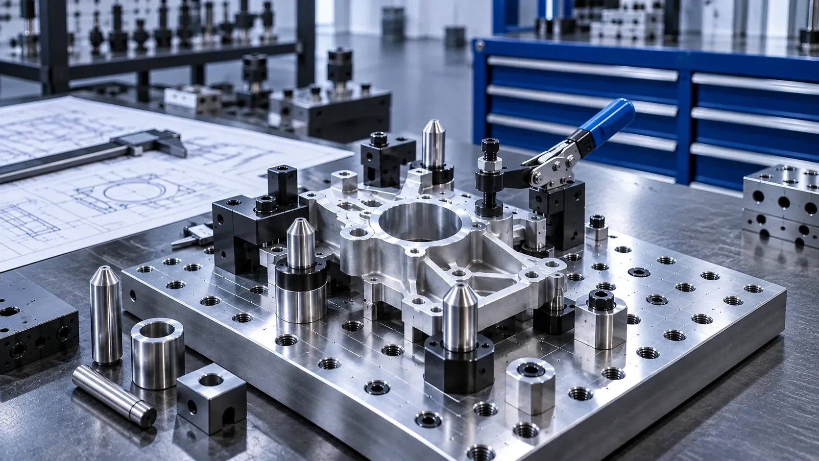
A practical guide to locating components for assembly and inspection tooling, covering datum location, two-hole positioning, loading, lead-in geometry, wear and replaceable interfaces.

Locating Components for Assembly & Inspection Tooling
Assembly and inspection tooling often performs the same basic task many times: load a part, establish its position, complete the operation, remove it and repeat.
The locating components may be small, but they directly affect how easily the workpiece loads and whether it returns to the intended position from cycle to cycle.
A locating arrangement that is unnecessarily restrictive can cause binding. Too much clearance can make loading easy but weaken the intended locating function. Poor entry geometry can slow manual loading, while repeated contact can eventually wear the mating interface.
The right design starts by defining how the workpiece should be located and how it will actually be loaded.
1. Start with the datum strategy
Before selecting a locating pin, determine which workpiece features will establish its position.
Depending on the tooling, location may be established from:
- existing holes in the workpiece;
- external edges or profiles;
- machined datum features;
- a combination of supports and locating points.
For hole-based location, the objective is not simply to fill every available hole with a tight-fitting pin.
Each locating feature should have a defined function.
Ask:
- Which feature establishes the primary position?
- Which feature controls orientation?
- Which directions must remain free to avoid redundant constraint?
- What variation exists between the workpiece features?
This is especially important when two workpiece holes are used for location.
2. Why use round and diamond locating pins for two-hole location?
Using two full round pins in two workpiece holes can create a problem.
Even when each individual hole and pin is within tolerance, variation in the center distance between the two holes can make the workpiece difficult or impossible to load.
A common solution is:
one round locating pin + one diamond locating pin.
The round pin acts as the primary locator and controls position in two axes. The diamond pin is relieved so that it controls the remaining required direction without redundantly constraining the workpiece.
Carr Lane describes this arrangement specifically as a way to locate two holes accurately while avoiding binding caused by redundant location.
This does not mean every two-hole workpiece automatically requires a round-and-diamond arrangement.
The correct fit and locating scheme still depend on the workpiece geometry, tolerances and required function.
3. Make repeated loading easier
An assembly or inspection tool may be geometrically correct and still be frustrating to use.
This often happens when the workpiece approaches the locating pin with some initial misalignment.
Possible symptoms include:
- the operator has to wiggle the part into position;
- the workpiece catches on the pin edge;
- loading becomes slow;
- the locating feature is struck repeatedly during insertion;
- automated loading becomes sensitive to small approach errors.
In these cases, the entry geometry deserves attention.
A chamfered, tapered or bullet-nose locating pin can provide a larger initial entry zone and guide the workpiece toward the final locating interface.
MISUMI specifically describes bullet-nose pins as helping prevent binding and facilitating insertion and removal of workpieces.
The important distinction is:
Lead-in geometry helps the part enter.
The final locating geometry establishes the position.
Do not create excessive final clearance simply to compensate for difficult loading.
4. Consider the loading sequence
If multiple locating points engage at exactly the same time, the operator or handling system may have to align all of them simultaneously.
Depending on the tooling design, it can be easier for one locating feature to begin guiding the workpiece before the remaining feature fully engages.
When reviewing the loading sequence, consider:
- approach direction;
- workpiece orientation;
- whether loading is manual or automated;
- effective engagement heights;
- lead-in geometry;
- visibility of the locating points;
- clearance around the workpiece.
The goal is to make the transition from rough placement to final location predictable.
This becomes increasingly important as loading frequency increases.
5. Do not solve loading problems only by increasing clearance
When a part is difficult to load, increasing the pin-to-hole clearance can appear to be the easiest solution.
But that change can affect the locating relationship.
Before changing clearance, determine why loading is difficult.
The actual cause may be:
- redundant constraint;
- hole-spacing variation;
- insufficient lead-in;
- poor approach alignment;
- damaged locating surfaces;
- contamination;
- wear;
- incorrect pin geometry.
Treating all of these as a clearance problem can make the tooling easier to load while introducing unnecessary positional variation.
Review the locating scheme first, then determine the appropriate fit for the actual application.
6. Use replaceable interfaces where wear is expected
Assembly and inspection tooling can see repeated workpiece loading over its service life.
The same surfaces may contact thousands of times.
Wear can occur at:
- locating pins;
- workpiece contact points;
- mating holes;
- guide bushings;
- mounting interfaces.
If the tooling base itself becomes the wear surface, maintenance can become more difficult.
A replaceable locating or guide bushing can provide a serviceable mating interface where appropriate.
Locating pins are also commonly designed for use either directly or together with bushings or pin holders.
When planning the tooling, ask:
Which component should be replaced when this interface eventually wears?
That question is easier to answer during design than after positional consistency has already deteriorated.
7. Distinguish locating from clamping
A workpiece can be correctly located without being securely retained.
Likewise, a clamp can hold a workpiece firmly without establishing its intended position.
These are different functions:
Locating establishes where the workpiece is.
Clamping or retention keeps it there during the operation.
Carr Lane's check-fixture offering reflects this distinction: locating pins and round/diamond locating pins are provided alongside separate clamping components such as toggle clamps.
When diagnosing inconsistent assembly or inspection results, check both functions separately.
Increasing clamping force is not a substitute for correcting an undefined locating scheme.
8. Design differently for manual and automated loading
Manual and automated loading can use the same basic locating principles, but their practical requirements differ.
Manual loading
Consider:
- operator visibility;
- hand clearance;
- intuitive part orientation;
- easy initial engagement;
- avoiding sharp or obstructive features;
- easy removal after the operation.
Automated loading
Consider:
- approach repeatability;
- robot or transfer-system positioning variation;
- lead-in geometry;
- engagement sequence;
- interference during insertion;
- sensor or confirmation requirements elsewhere in the machine design.
MISUMI identifies locating pins as components used in both semi- and fully automated manufacturing where workpieces need to be positioned before processing.
In both cases, the locating interface should tolerate the expected initial placement variation while still establishing the required final position.
9. Common assembly and inspection tooling problems
The workpiece binds on two locating pins
Review whether the tooling is redundantly constraining two workpiece holes.
A round-and-diamond locating strategy may be appropriate where the geometry requires two-hole location while accommodating center-distance variation.
The operator has to wiggle the part into position
Check the initial alignment and lead-in geometry.
A bullet-nose or tapered entry may improve engagement without simply increasing final locating clearance.
Loading is easy, but the part position varies too much
Review whether excessive clearance was introduced to solve an insertion problem.
The lead-in and final locating interface should be considered separately.
Positioning becomes less consistent after extended use
Inspect the pin and mating surfaces for wear, damage and contamination.
Where appropriate, use replaceable wear components rather than allowing the tooling structure itself to become the sacrificial interface.
The part is located correctly but moves during the operation
Review the retention or clamping strategy.
The problem may not be the locating components.
A replacement workpiece no longer fits the tooling easily
Review actual workpiece feature variation and the locating scheme rather than assuming the new batch is identical to the original parts.
10. What information should be included in an RFQ?
For locating components used in assembly or inspection tooling, provide as much of the following information as possible:
- component type or existing part number;
- workpiece or tooling drawing;
- locating-hole diameter;
- distance between locating features;
- pin diameter and head geometry, if already specified;
- round or diamond locating requirement;
- mounting or shank style;
- required engagement length;
- mating bushing information;
- material requirement;
- manual or automated loading;
- expected operating frequency;
- quantity;
- existing component information for replacement applications.
For a new tooling project, the relevant section of the workpiece drawing can be particularly useful because the locating strategy depends on the features being used as datums.
11. Match the component to the tooling problem
A practical starting point is:
Need to establish a workpiece datum from a hole?
Review Round Locating Pins.
Need two-hole location while reducing redundant constraint?
Review Round & Diamond Locating Pins.
Need easier initial insertion?
Review Bullet-Nose or Tapered Locating Pins.
Need a replaceable mating or wear interface?
Review the appropriate Locating / Guide Bushing.
Need repeatable adjustable tooling positions rather than fixed workpiece location?
Review Indexing Components separately.
The component should be selected according to its role in the locating system, not simply according to the nearest matching diameter.
Design the tooling around repeatable loading
For assembly and inspection tooling, reliable positioning begins before the workpiece reaches its final location.
Think through the complete sequence:
Approach → Guide → Locate → Retain → Operate / Inspect → Release
Then review the datum strategy, workpiece variation, lead-in geometry, mating interface and expected wear.
If you are selecting locating components for a new assembly or inspection tool—or replacing an existing locating pin—send the drawing, existing part number or key dimensions for component review and quotation.